Your shopping cart is empty!
 Robot and Robot Kit
 Robot Controller
 Servo Controller
 Motor Controller and Driver
 Computer Interface
 Sensors
 Arduino
 Arduino Shield and Accessories
 RC Interface
 Display
 Prototyping
 Voltage Regulator
 Miscellaneous
 Ball Casters
 Switches
 Servo
Servo LEDs
LEDs Headers
Voltage Regulator
Display: List / Grid


Overview
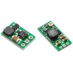
The Pololu adjustable boost regulator is a ..
$11.95
Overview
The Pololu adjustable boost regulator is a ..
$11.95

Note: Pololu has released newer D24V90F5 5V, 9A step-down voltage regulators, D24V60F5 5V, 6A s..
$24.95
Showing 1 to 4 of 4 (1 Pages)
Powered By OpenCart
RobotSimple © 2026
RobotSimple © 2026