Your shopping cart is empty!
 Robot and Robot Kit
 Robot Controller
 Servo Controller
 Motor Controller and Driver
 Computer Interface
 Sensors
 Arduino
 Arduino Shield and Accessories
 RC Interface
 Display
 Prototyping
 Voltage Regulator
 Miscellaneous
 Ball Casters
 Switches
 Servo
Servo LEDs
LEDs Headers
 Black or Green")
16x2 Character LCD with LED Backlight (Parallel Interface) Black or Green
Product Code: 00070
Availability: Currently Unavailable
Availability: Currently Unavailable
Price: $12.95
 |
Overview
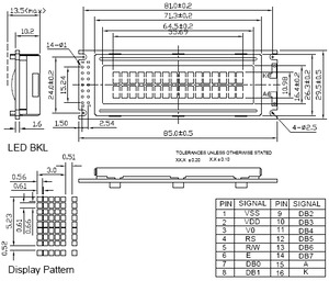
This 16-character, 2-line parallel liquid crystal display achieves a large viewing area in a compact package. It features a yellow-green LED backlight and uses the common HD44780 interface (330k pdf), so sample interface code is widely available for a variety of microcontrollers. This LCD is also available without a backlight.
The DDRAM address 0x00 corresponds to the first character of the top line, address 0x0F corresponds to the last character of the top line, address 0x40 corresponds to the first character of the second line, and address 0x4F corresponds to the last character of the second line.
You can find sample HD44780 LCD interface code written for a variety of AVR microcontrollers as part of the Pololu AVR library.
 |
 |
Pinout
| Pin | Symbol | Function |
|---|---|---|
| 1 | Vss | ground (0 V) |
| 2 | Vdd | 5 V logic supply voltage |
| 3 | Vo | contrast adjustment |
| 4 | RS | H/L register select signal |
| 5 | R/W | H/L read/write signal |
| 6 | E | H/L enable signal |
| 7-14 | DB0 – DB7 | H/L data bus for 4- or 8-bit mode |
| 15 | A (LED+) | backlight anode |
| 16 | K (LED-) | backlight cathode |
Using Contrast and the Backlight
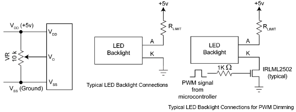 |
As shown in the diagram above, a potentiometer whose output is connected to Vo will allow you to set the contrast for optimal viewing of your display.
The backlight in this LCD is composed of LEDs in series. The total voltage drop across these LEDs is typically 4.2 V and the recommended current through the LEDs is 120 mA. You should use a current limiting resistor RLIMIT as shown above where:
RLIMIT = (VBACKLIGHT – 4.2V) / 0.12A
In the diagram above, VBACKLIGHT is shown as 5 V, but you are not restricted to 5 V; any voltage above the diode-drop voltage will work as long as you choose the appropriate value for your current-limiting resistor. You can also use a PWM-controlled MOSFET to achieve variable dimming of the backlight if so desired.
Note: No cables or connectors are included with this product, but a 40×2-pin 0.100" male header strip and 20", 16-conductor ribbon cable can be purchased separately. You can break a 7×2 segment from the header strip and solder it to the 14 through-holes on the left side of the LCD PCB; the ribbon cable will then plug into the header pins (leaving two holes empty). The header pins won’t enforce proper orientation of the cable, so you will need to take care to plug it into the correct pins. The 8×2 shrouded box header can be used with this LCD if you use pliers to pull out connector pins 15 and 16, effectively turning it into a 7×2 keyed receptacle for a 16-conductor ribbon cable.
Powered By OpenCart
RobotSimple © 2026
RobotSimple © 2026