Your shopping cart is empty!
 Robot and Robot Kit
 Robot Controller
 Servo Controller
 Motor Controller and Driver
 Computer Interface
 Sensors
 Arduino
 Arduino Shield and Accessories
 RC Interface
 Display
 Prototyping
 Voltage Regulator
 Miscellaneous
 Ball Casters
 Switches
 Servo
Servo LEDs
LEDs Headers
")
Pololu RC Switch with Digital Output (rcs01a)
Product Code: 00067
Availability: Discontinued
Availability: Discontinued
Price: $777.00
Note: Pololu has released a newer version of the RC Switch with Digital Output, which is better than this product in almost every way and should be a drop-in replacement in most cases. This product is now only available by large-volume special order. Please contact Pololu for more information.
Overview
 |
The Pololu RC switch with digital output can be used with standard hobby radio control systems for radio control switch applications or simple interface applications. Example applications include converting extra RC receiver or servo controller outputs to simple high/low signals that can control LEDs or MOSFETs or relays and connecting RC systems to microcontroller projects that do not have the necessary resources for decoding the RC interface. Two outputs indicate the presence of a valid signal and whether the switch is on or off. This compact unit measures a mere 0.4" x 0.4" and weighs just 0.3 g (0.01 oz).
Using the RC Switch
Connections
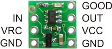 |
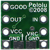
The RC switch PCB has two sets of connections, one on each side. The side with three pins can connect directly to an RC receiver or servo controller; the side with four pins has the board power supply connections and two outputs. The outputs will be at the same levels as the VCC power connection, which can range from 2.0 V to 5.5 V. The RC signal input, IN, voltage can range from 0 to 7 V, and the threshold for a logic high is approximately 1 V. The VCC pin can be connected to the RC supply, VRC, by shorting across the appropriate pads on the back side of the PCB, allowing either the RC receiver to power the digital device or allowing the digital system to power the RC receiver (if the connection between the two power pins is not made, VRC can be left disconnected since it is not used by the RC switch board).
Outputs and Indicator LED
The board has two outputs, each of which is capable of sourcing or sinking 20 mA. The primary output, OUT, goes high (on) when a valid signal is detected and the pulse width is above the threshold of 1.6 ms. There is approximately ±0.1 ms of hysteresis on the threshold, meaning that the pulse width will have to get to approximately 1.7 ms before the output turns on, and once on, the signal will have to fall below 1.5 ms to turn off. A secondary output, GOOD, can be used to indicate the presence of a valid RC signal (10-100 Hz pulse rate, 0.5-2.5 ms pulse width).
An LED on the RC switch indicates the status of the RC signal (and outputs). When a valid RC signal is not detected (GOOD and OUT both low), the LED flashes with a duty cycle of approximately 50% (i.e. the LED is on for as long as it is off). When a valid signal is detected but the pulse width is below the threshold (GOOD high and OUT low), the LED flashes at a very low duty cycle (i.e. very short flashes). When a good signal is detected and the pulse width is above the threshold, both outputs are high and the LED turns on (no flashing).
Included Hardware
A 7-pin 0.1" straight breakaway male header is included with the Pololu RC switch with digital output, which can be used to connect the RC switch to perfboards or breadboards.
Powered By OpenCart
RobotSimple © 2026
RobotSimple © 2026